8.9 Heating a room
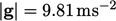
A simulation of heating a room demonstrates natural convection driven by buoyancy forces. An idealised, ground floor room is presented below, with external glass doors and sloping roof, and internal walls and ceiling.
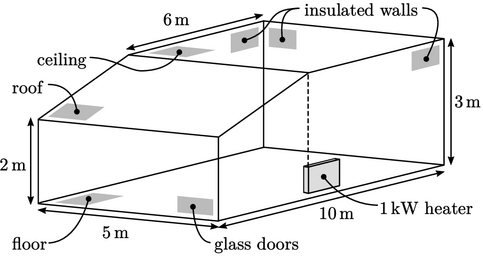
A heater is located along one side wall, below
the point where the roof and ceiling meet. The aim of the
simulation was to calculate the room temperature with the heater
running at 1kW, when the ambient external temperature  .
.
The thermal boundary conditions were specified as
follows: floor temperature  ; ceiling
  , representing the first
floor temperature; insulated walls, with
, representing the first
floor temperature; insulated walls, with  , see
Sec. 4.17
; glass doors and
roof with a heat flux according to Eq. (4.30
) using
, see
Sec. 4.17
; glass doors and
roof with a heat flux according to Eq. (4.30
) using  and
and  ,
respectively.
,
respectively.
The mesh contained 350,000 hexahedral cells with
grading that gave a cell height of approximately  along the walls.
Transport properties for air,  and
and  , were used. Turbulence
was modelled using the
, were used. Turbulence
was modelled using the  SST model described in Sec. 7.11
, with initial levels
of
SST model described in Sec. 7.11
, with initial levels
of  and
and  . The near-wall cell centres corresponded to
  , so the continuous
wall function from Sec. 7.6
and thermal
wall function from Sec. 7.14
were applied at
the boundaries.
, so the continuous
wall function from Sec. 7.6
and thermal
wall function from Sec. 7.14
were applied at
the boundaries.
The simulation used the transient solution
algorithm in Sec. 5.19
, including the buoyancy force
 in
Eq. (2.67
), with
in
Eq. (2.67
), with
 .
The condition
.
The condition  was applied at all boundaries, combined with the flux
calculation in Eq. (5.20
).
was applied at all boundaries, combined with the flux
calculation in Eq. (5.20
).
The variations in  within
  were calculated
using the ideal gas Eq. (2.55
) using
were calculated
using the ideal gas Eq. (2.55
) using  .
.
The simulation ran with a time step
 .
The flow is highly unsteady, but at
.
The flow is highly unsteady, but at  the heat losses
through the boundaries oscillate about the mean levels indicated
above.
the heat losses
through the boundaries oscillate about the mean levels indicated
above.
Between the ground and 2m, occupants experience a
variation in  . In the space adjacent to the roof and ceiling, the
higher
. In the space adjacent to the roof and ceiling, the
higher  generates significant heat losses, especially to the outside
through the roof.
generates significant heat losses, especially to the outside
through the roof.