7.3 Inlet turbulence
Expressions are presented in Sec. 7.2
to estimate inlet and
initial values of  and
and  . They include parameters
  and
and  which must
themselves be estimated sufficiently accurately to calculate
which must
themselves be estimated sufficiently accurately to calculate
 and
and  reliably.
The values of  and
and  at domain inlets
depend on the flow conditions upstream of the inlet. The figure below
shows typical ranges of intensity
at domain inlets
depend on the flow conditions upstream of the inlet. The figure below
shows typical ranges of intensity  for different upstream
flow conditions.
for different upstream
flow conditions.
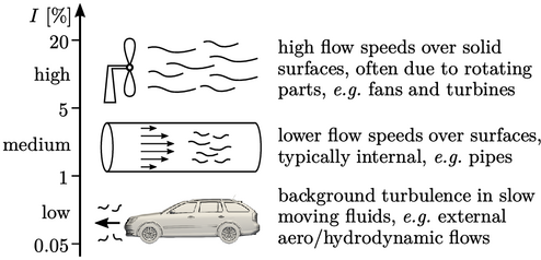
A medium intensity 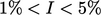 is most commonly
specified in CFD problems, in particular for internal flows. For
these flows,
is most commonly
specified in CFD problems, in particular for internal flows. For
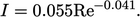
these flows,  can be calculated from a power-law function of
 ,
fitted to measurements at the central axis in fully developed flow
along a smooth-wall pipe, according to4
,
fitted to measurements at the central axis in fully developed flow
along a smooth-wall pipe, according to4
 |
(7.7) |
 at the centre axis of a pipe, see Sec. 6.12
, can be used in
conjunction with
at the centre axis of a pipe, see Sec. 6.12
, can be used in
conjunction with  from of Eq. (7.7
). For ducts and
channels of non-circular cross-section,
from of Eq. (7.7
). For ducts and
channels of non-circular cross-section,  can be calculated by
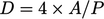 ,
where
,
where  is the cross-sectional area and
  is the perimeter
length. For a partially filled pipe or duct,
is the perimeter
length. For a partially filled pipe or duct,  corresponds to the
wetted region where the fluid is in contact with the boundary.
corresponds to the
wetted region where the fluid is in contact with the boundary.
For wall-bounded flows with a boundary layer of
thickness  , an estimate of
 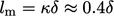 is often used. This relation (see also
Sec. 6.12
) requires
is often used. This relation (see also
Sec. 6.12
) requires  to be estimated,
e.g. from the
to be estimated,
e.g. from the  expression for
a turbulent layer at the end of Sec. 6.4
.
expression for
a turbulent layer at the end of Sec. 6.4
.
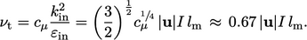
Verifying turbulent viscosity
Combining Eq. (7.4
), Eq. (7.6
) and Eq. (6.31
) gives the following
expression for  in terms of length
  and velocity
 scales:
 |
(7.8) |
 need to be realistic. Realistic values usually fall within
the range of molecular viscosities
need to be realistic. Realistic values usually fall within
the range of molecular viscosities  for common fluids at standard temperature shown below.
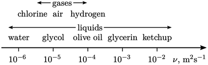
The range is presented in terms of kinematic viscosity  which governs the
rate of momentum
diffusion, e.g. the rate of growth of boundary
layers. By contrast, forces
are governed by dynamic viscosity
which governs the
rate of momentum
diffusion, e.g. the rate of growth of boundary
layers. By contrast, forces
are governed by dynamic viscosity  , which make liquids
“feel” more viscous.
, which make liquids
“feel” more viscous.