8.1 External flows
This chapter includes examples of flow around a cylinder and automotive aerodynamics. They are examples of external flows, which are characterised by a lack of solid boundaries to define the extent of some part, or all, of the solution domain.
The cost of a CFD simulation increases with the size of the computational mesh, so we cannot afford to have a solution domain which extends indefinitely in some direction. Boundaries must to be drawn somewhere, but which locations are optimal?
To calculated forces on a body accurately, the
external boundaries need to positioned a surprisingly long distance
from the body. For example, CFD calculations of forces on an
aerofoil have used a domain length of 1000 the aerofoil chord
length.
To understand why large distances are necessary, we must first recognise that the pressure is imposed at external boundaries according to the applied boundary conditions. Thy can include a fixed value outflow condition in Sec. 4.3 , a total pressure condition in Sec. 4.7 , a freestream condition in Sec. 4.16 , etc.
The pressure at external boundaries will inevitably differ from the pressure at the same location in an unbounded problem. As discussed in Sec. 2.22 , a change in pressure at any point influences the pressure everywhere in the solution domain, so any discrepancies in boundary pressures are reflected in the force calculations, including the shear forces.
Larger solution domains yield smaller discrepancies in pressure, producing solutions that better represent an unbounded domain. Accepting large domains are necessary, we need to limit the computational cost with an efficient meshing strategy that combines smaller cells to resolve higher gradients in complex, transient flow regions, with larger cells where the flow is more uniform.
Mesh refinement
An external flow approaches far-field freestream conditions in regions around the external boundaries. Larger cells are effective in these regions since the flow is fairly uniform; smaller cells can then be reserved for more critical regions, close to, and in the wake of, solid bodies.

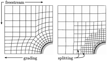
Two common ways to vary cell size are shown above. To the left is an example of a structured mesh which increases the cell lengths towards the freestream boundaries. The transition in size is smooth but cells tend to be generated which are noticeably longer in one direction than another, i.e. with a high aspect ratio, discussed in more detail in the following section.
To the right is an example of a mesh which refines the mesh away from the freestream boundaries using cell splitting. Starting from a coarse mesh, the method reduces the cell size by splitting each cell into two in each direction. This approach produces more abrupt changes in cell size across refinement interfaces, but maintains lower aspect ratios in the cells.

