4.6 Free (entrainment) boundaries
The basic set of boundary conditions for subsonic incompressible flow, introduced in Sec. 4.3 , relates to inlet, outlet and wall boundary regions. Sometimes a single boundary patch occupies a location which experiences both inflow and outflow.

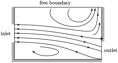
The figure above shows a 2D domain with an inlet and outlet, left and right respectively. The top boundary is free to allow:
- inflow from the centre to the left side of the patch, through entrainment of fluid by the main flow from the inlet;
- outflow at the right side of the patch, driven by a pressure gradient that emanates from the point where the flow impinges on the right wall.
Boundary conditions for  and
and  are therefore
required which support both inflow and outflow at a single patch. The
inlet flow speed is determined from the flow solution rather than
being prescribed at the patch. This suggests a gradient condition
on
  , which is generally prescribed at an outlet.

At a free/entrainment boundary, the basic
outflow conditions,  and
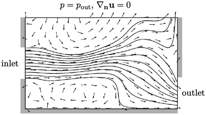
and  , are generally not recommended. The figure above shows a
snapshot from a simulation using those conditions. The solution
oscillates between changing levels of inflow and outflow over the
open boundary; the figure below shows the flow leading up to the
snapshot above.

The is no convergence towards a stable solution in this example of a simple flow in a regular 2D geometry. Moreover, solutions tend to diverge and “blow up” if the basic outflow conditions are applied at a free boundary for geometries and meshes that are even moderately complex. In the following sections we look at some alternative conditions that are applied at a free boundary to deliver stable, robust solutions.

