3.2 Computational mesh
A CFD simulation begins with a solution domain which specifies a region of space of a particular geometric shape, in which fluid dynamics equations are solved. For example, when simulating flow along a pipe, the solution domain would be some region of space occupied by the fluid within the pipe.
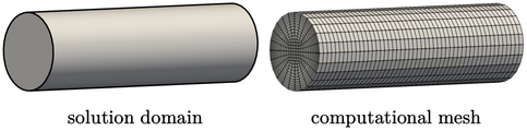
The process of mesh generation subdivides the solution domain into a mesh of small volumes, or cells. Computer programs are used to create the cells according to some user specification. We discuss neither mesh generation software nor any underlying methods they use. Rather, we define the structure and properties of a valid mesh in this chapter and some aspects of the design of optimal meshes in Chapter 8 .
Polyhedral mesh
Meshes in modern CFD software, that use the
finite volume method, can contain cells of any irregular polyhedral
shape. A cell can consist of an unlimited number of faces
( 4) and each face can have an unlimited number of edges
(
4) and each face can have an unlimited number of edges
( 3).
3).
Cells are contiguous, i.e. the faces of a given cell are common to its neighbouring cells (unless they form the boundary of the solution domain). There is no restriction on the alignment of cells with co-ordinate axes.
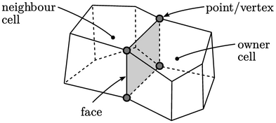
The figure above shows two cells connected by a common face displayed in grey. Every face is defined by a list of vertices that follow edges in sequence around the face.
Each face inside the mesh is common to two cells, one known as the owner cell, the other the neighbour cell. At the domain boundary, each face is connected to one owner cell. By assigning a unique index to each cell, the connectivity between cells can represented by storing the indices of the owner and neighbour cell of each face.
The cell faces that describe the domain boundary are separated into groups, each with a unique name. Each named group of boundary faces, known as a patch, identifies a specific region of the domain boundary, to enable us to apply specific boundary conditions to that region when running a CFD simulation.
A mesh is therefore defined by the following:
- a list of every vertex used to define all faces;
- a list of faces, each defined by a sequence of vertex indices;
- a list of owner cell indices associated with the faces;
- a list of neighbour cell indices associated with faces;
- grouping boundary faces into a set of patches.