8.3 Block-structured meshes
This section describes the generation of meshes for cases with boundaries formed by relatively simple geometric shapes, e.g. a cylinder, such as the examples in Sec. 8.4 and Sec. 8.8 .
Block-structured mesh generation involves splitting the domain (assumed 3D) into several 6-sided blocks. Each block is then divided into a number of hexahedral-shaped cells.
There are some popular strategies for specifying
the structure of blocks around boundaries of particular shapes. The
most general approach uses blocks which extend outwards from
sections of the boundary into the domain. For a cylinder in
cross-section, 4 blocks are typically used as shown below by the
blocks whose edges are oriented at  to the horizontal.
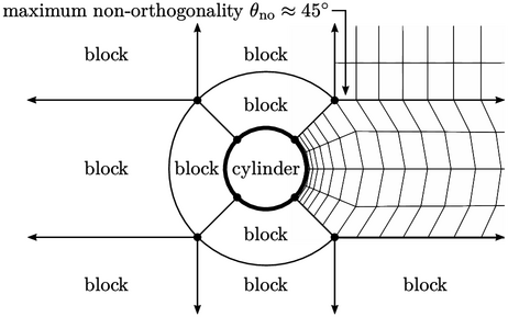
The domain extends away from the cylinder with
additional blocks connected to those that encircle the cylinder.
The mesh is usually graded starting with small cell heights on the
cylinder surface, which gradually increase with distance from the
surface. The main weakness of this block structure is the abrupt
transition in non-orthogonality from  to
to  at the outer
vertices of the inner blocks, indicated in the figure.
at the outer
vertices of the inner blocks, indicated in the figure.
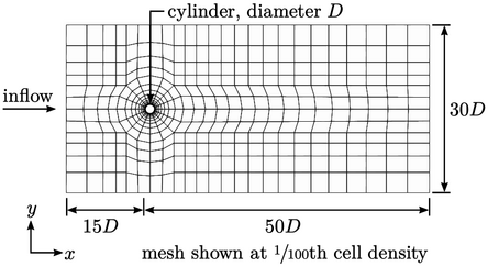
The figure above shows the structure of the mesh
of 40,000 cells used in Sec. 8.4
for a cylinder of diameter
 .
Each element represents 10
.
Each element represents 10 10 = 100 cells in the actual mesh. There are
80 layers of cells around the cylinder, with grading that gives a
centre height of
10 = 100 cells in the actual mesh. There are
80 layers of cells around the cylinder, with grading that gives a
centre height of  in cells adjacent to the cylinder surface.
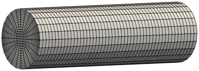
A mesh inside a cylinder, e.g. a pipe, can use a similar structure in which the inner vertices of the curved blocks are connected to form a single block along the centre, as shown above.