[version 14][version 13][version 12][version 11][version 10][version 9][version 8][version 7][version 6]
5.3 Mesh boundary
As we saw in section 5.2 , the domain boundary is defined by patches within the mesh, listed within the boundary mesh file. Each patch includes a type entry which can apply a geometric constraint to the patch. These geometric constraints include conditions that represent a geometric approximation, e.g. a symmetry plane, and conditions which form numerical connections between patches, e.g. a cyclic (or periodic) boundary. An example boundary file is shown below which includes some patches with geometric constraints.
175
18(
19 top
20 {
21 type wall;
22 inGroups List<word> 1(wall);
23 nFaces 60;
24 startFace 3510;
25 }
26 inlet
27 {
28 type patch;
29 nFaces 30;
30 startFace 3570;
31 }
32 outlet
33 {
34 type patch;
35 nFaces 30;
36 startFace 3600;
37 }
38 bottom
39 {
40 type symmetryPlane;
41 inGroups List<word> 1(symmetryPlane);
42 nFaces 60;
43 startFace 3630;
44 }
45 frontAndBack
46 {
47 type empty;
48 inGroups List<word> 1(empty);
49 nFaces 3600;
50 startFace 3690;
51 }
52)
53
54// ************************************************************************* //
A type entry is specified for every patch (inlet, outlet, etc.), with types assigned that include patch, wall, symmetryPlane and empty. Some patches also include an inGroups entry which is discussed in section 5.3.6 .
5.3.1 Generic patch and wall
The patch types specified in the boundary file, which are not associated with a geometric constraint are the generic patch and wall. The patch type is assigned to open boundaries such as an inlet or outlet which does not involve any special handling of geometric approximation or numerical connections.
The wall type also provides no special geometric or numerical handling, but is used for patches which coincide with a solid wall. The wall ‘tag’ is required by some models, e.g. wall functions in turbulence modelling which require the distance to nearest wall.
5.3.2 1D/2D and axi-symmetric problems
OpenFOAM is designed as a code for 3D space and defines all meshes as such. However, 1D and 2D and axi-symmetric problems can be simulated in OpenFOAM by generating a mesh in 3 dimensions and applying special boundary conditions on any patch in the plane(s) normal to the direction(s) of interest. 1D and 2D problems apply the empty patch type to the relevant patches. Often the two regions of the boundary, on the ‘front’ and ‘back’ of the domain, are combined into a single patch, as in the frontAndBack patch in the quoted example above.
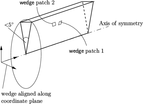
For axi-symmetric cases, the geometry,
e.g. a cylinder, is
approximated by a wedge-shaped mesh of small angle (e.g.  ) and 1 cell thick,
running along the centre line, straddling one of the coordinate
planes, as shown in Figure 5.2
. The axi-symmetric
wedge planes must be specified as separate patches of wedge type. The generation of wedge geometries for
axi-symmetric problems is discussed in section 5.4.10
.
) and 1 cell thick,
running along the centre line, straddling one of the coordinate
planes, as shown in Figure 5.2
. The axi-symmetric
wedge planes must be specified as separate patches of wedge type. The generation of wedge geometries for
axi-symmetric problems is discussed in section 5.4.10
.
5.3.3 Symmetry condition
A symmetry plane is a boundary condition that imagines the solution within the domain is ‘mirrored’ across the boundary. It can therefore be applied reliably to a domain with a plane of symmetry where the flow is believed to be symmetric across the plane. When the flow involves something like vortex shedding that breaks symmetry, the condition is less applicable.
There are two patch types relating to symmetry. Firstly, the symmetryPlane condition is a pure symmetry plane which can only be applied to a patch which is perfectly planar. There is then a symmetry condition, which can be applied to any patch, including those that are non-planar.
5.3.4 Cyclic conditions
The cyclic boundary conditions form a numerical connections between patches that are physically disconnected. The cyclic condition connects patches which have the same area to within a tolerance given by the matchTolerance keyword. Each patch specifies the name of the patch to which it connects through the neighbourPatch keyword. The condition can transform the field between patches, e.g. by a rotation, so the patches do not require the same orientation.
OpenFOAM also includes non-conformal coupling (NCC) which connects regions of a domain with independent meshes. It is and is used particularly for cases when one or more regions are moving, e.g. to simulate rotating geometry. Non-conformal coupling uses the nonConformalCyclic condition which are usually generated with the createNonConformalCouples utility. NCC examples can be located by searching for the createNonConformalCouples utility in Allrun scripts in the tutorials directory, e.g. by running
find $FOAM_TUTORIALS -name Allrun | \
xargs grep -l createNonConformalCouples
5.3.5 Processor patches
Running applications in parallel is described in section 3.4 . It involves decomposition of the mesh using decomposePar as described in section 3.4.1 . Decomposition splits the domain which creates new patches at the exposed faces. Those patches are assigned the processor type which forms a numerical connection between sub-domains. Each processor patch entry in the boundary file includes a myProcNo entry for the processor (sub-domain) index and a neighbProcNo entry for the index of the matching patch on the sub-domain it connects with.
5.3.6 Patch groups
The boundary file example shows some patches include an inGroups entry, e.g. the top patch:
top
{
type wall;
inGroups List<word> 1(wall);
nFaces 60;
startFace 3510;
}
Every non-generic patch, i.e. one which is not patch type, is included in a patch group of the same name as its type. For example, a patch of type wall is included in a wall group, one of type symmetry is included in a symmetry group, etc. The use of group names to specify boundary conditions in described further in chapter 6 .
5.3.7 Constraint type examples
The user can scan the tutorials for mesh generation configuration files, e.g. blockMeshDict for blockMesh (see section 5.4 ) and snappyHexMeshDict for snappyHexMesh (see section 5.5 , for examples of different types being used. The following example provides documentation and lists cases that use the symmetryPlane condition.
foamInfo -a symmetryPlane
find $FOAM_TUTORIALS -name snappyHexMeshDict | \
xargs grep -El "type[\t ]*wall"