[version 14][version 13][version 12][version 11][version 10][version 9][version 8][version 7][version 6]
5.4 Mesh generation with the snappyHexMesh utility
This section describes the mesh generation utility, snappyHexMesh, supplied with OpenFOAM. The snappyHexMesh utility generates 3-dimensional meshes containing hexahedra (hex) and split-hexahedra (split-hex) automatically from triangulated surface geometries, or tri-surfaces, in Stereolithography (STL) or Wavefront Object (OBJ) format. The mesh approximately conforms to the surface by iteratively refining a starting mesh and morphing the resulting split-hex mesh to the surface. An optional phase will shrink back the resulting mesh and insert cell layers. The specification of mesh refinement level is very flexible and the surface handling is robust with a pre-specified final mesh quality. It runs in parallel with a load balancing step every iteration.
5.4.1 The mesh generation process of snappyHexMesh
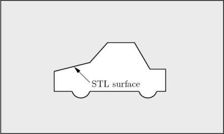
The process of generating a mesh using snappyHexMesh will be described using the schematic in Figure 5.8. The objective is to mesh a rectangular shaped region (shaded grey in the figure) surrounding an object described by a tri-surface, e.g. typical for an external aerodynamics simulation. Note that the schematic is 2-dimensional to make it easier to understand, even though the snappyHexMesh is a 3D meshing tool.
In order to run snappyHexMesh, the user requires the following:
- one or more tri-surface files located in a constant/triSurface sub-directory of the case directory;
- a background hex mesh which defines the extent of the computational domain and a base level mesh density; typically generated using blockMesh, discussed in section 5.4.2.
- a snappyHexMeshDict dictionary, with appropriate entries, located in the system sub-directory of the case.
The snappyHexMeshDict dictionary includes: switches at the top level that control the various stages of the meshing process; and, individual sub-directories for each process. The entries are listed below.
- castellatedMesh: to switch on creation of the castellated mesh.
- snap: to switch on surface snapping stage.
- addLayers: to switch on surface layer insertion.
- mergeTolerance: merge tolerance as fraction of bounding box of initial mesh.
- geometry: sub-dictionary of all surface geometry used.
- castellatedMeshControls: sub-dictionary of controls for castellated mesh.
- snapControls: sub-dictionary of controls for surface snapping.
- addLayersControls: sub-dictionary of controls for layer addition.
- meshQualityControls: sub-dictionary of controls for mesh quality.
All the geometry used by snappyHexMesh is specified in a geometry sub-dictionary in the snappyHexMeshDict dictionary. The geometry can be specified through a tri-surface or bounding geometry entities in OpenFOAM. An example is given below:
{
sphere1 // User defined region name
{
type triSurfaceMesh;
file "sphere1.obj"; // surface geometry OBJ file
regions
{
secondSolid // Named region in the OBJ file
{
name mySecondPatch; // User-defined patch name
} // otherwise given sphere1_secondSolid
}
}
box1x1x1 // User defined region name
{
type searchableBox; // region defined by bounding box
min (1.5 1 -0.5);
max (3.5 2 0.5);
}
sphere2 // User defined region name
{
type searchableSphere; // region defined by bounding sphere
centre (1.5 1.5 1.5);
radius 1.03;
}
};
5.4.2 Creating the background hex mesh
Before snappyHexMesh is executed the user must create a background mesh of hexahedral cells that fills the entire region within by the external boundary as shown in Figure 5.9.
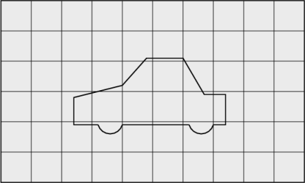
This can be done simply using blockMesh. The following criteria must be observed when creating the background mesh:
- the mesh must consist purely of hexes;
- the cell aspect ratio should be approximately 1, at least near surfaces at which the subsequent snapping procedure is applied, otherwise the convergence of the snapping procedure is slow, possibly to the point of failure;
- there must be at least one intersection of a cell edge with the tri-surface, i.e. a mesh of one cell will not work.
5.4.3 Cell splitting at feature edges and surfaces
Cell splitting is performed according to the specification supplied by the user in the castellatedMeshControls sub-dictionary in the snappyHexMeshDict. The entries for castellatedMeshControls are presented below.
- locationInMesh: location vector inside the region to be meshed; vector must not coincide with a cell face either before or during refinement.
- maxLocalCells: max number of cells per processor during refinement.
- maxGlobalCells: overall cell limit during refinement (i.e. before removal).
- minRefinementCells: if minRefinementCells
 number of cells to
be refined, surface refinement stops.
number of cells to
be refined, surface refinement stops.
- nCellsBetweenLevels: number of buffer layers of cells between successive levels of refinement (typically set to 3).
- resolveFeatureAngle: applies maximum level of refinement to cells that can see intersections whose angle exceeds resolveFeatureAngle (typically set to 30).
- features: list of features for refinement.
- refinementSurfaces: dictionary of surfaces for refinement.
- refinementRegions: dictionary of regions for refinement.
The splitting process begins with cells being selected according to specified edge features first within the domain as illustrated in Figure 5.10. The features list in the castellatedMeshControls sub-dictionary permits dictionary entries containing a name of an edgeMesh file and the level of refinement, e.g.:
(
{
file "features.eMesh"; // file containing edge mesh
level 2; // level of refinement
}
);
The edgeMesh containing the features can be extracted from the tri-surface file using the surfaceFeatures utility which specifies the tri-surface and controls such as included angle through a surfaceFeaturesDict configuration file, examples of which can be found in several tutorials and at $FOAM_ETC/caseDicts/surface/surfaceFeaturesDict. The utility is simply run by executing the following in a terminal
surfaceFeatures
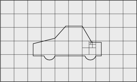
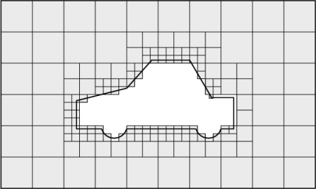
Following feature refinement, cells are selected for splitting in the locality of specified surfaces as illustrated in Figure 5.11.
The refinementSurfaces dictionary in castellatedMeshControls requires dictionary entries for each STL surface and a default level specification of the minimum and maximum refinement in the form (<min> <max>). The minimum level is applied generally across the surface; the maximum level is applied to cells that can see intersections that form an angle in excess of that specified by resolveFeatureAngle.
The refinement can optionally be overridden on one or more specific region of an STL surface. The region entries are collected in a regions sub-dictionary. The keyword for each region entry is the name of the region itself and the refinement level is contained within a further sub-dictionary. An example is given below:
{
sphere1
{
level (2 2); // default (min max) refinement for whole surface
regions
{
secondSolid
{
level (3 3); // optional refinement for secondSolid region
}
}
}
}
5.4.4 Cell removal
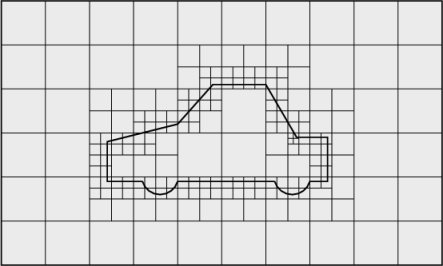
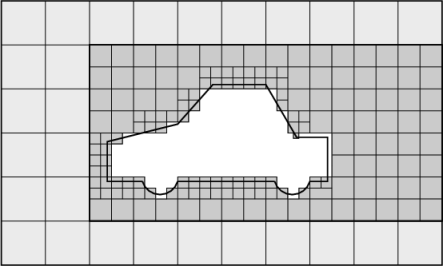
Once the feature and surface splitting is complete a process of cell removal begins. Cell removal requires one or more regions enclosed entirely by a bounding surface within the domain. The region in which cells are retained are simply identified by a location vector within that region, specified by the locationInMesh keyword in castellatedMeshControls. Cells are retained if, approximately speaking, 50% or more of their volume lies within the region. The remaining cells are removed accordingly as illustrated in Figure 5.12.
5.4.5 Cell splitting in specified regions
Those cells that lie within one or more specified volume regions can be further split as illustrated in Figure 5.13 by a rectangular region shown by dark shading. The refinementRegions sub-dictionary in castellatedMeshControls contains entries for refinement of the volume regions specified in the geometry sub-dictionary. A refinement mode is applied to each region which can be:
- inside refines inside the volume region;
- outside refines outside the volume region
- distance refines according to distance to the surface; and can accommodate different levels at multiple distances with the levels keyword.
For the refinementRegions, the refinement level is specified by the levels list of entries with the format(<distance> <level>). In the case of inside and outside refinement, the <distance> is not required so is ignored (but it must be specified). Examples are shown below:
{
box1x1x1
{
mode inside;
levels ((1.0 4)); // refinement level 4 (1.0 entry ignored)
}
sphere1
{ // refinement level 5 within 1.0 m
mode distance; // refinement level 3 within 2.0 m
levels ((1.0 5) (2.0 3)); // levels must be ordered nearest first
}
}
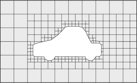
5.4.6 Snapping to surfaces
The next stage of the meshing process involves moving cell vertex points onto surface geometry to remove the jagged castellated surface from the mesh. The process is:
- displace the vertices in the castellated boundary onto the STL surface;
- solve for relaxation of the internal mesh with the latest displaced boundary vertices;
- find the vertices that cause mesh quality parameters to be violated;
- reduce the displacement of those vertices from their initial value (at 1) and repeat from 2 until mesh quality is satisfied.
The method uses the settings in the snapControls sub-dictionary in snappyHexMeshDict, listed below.
- nSmoothPatch: number of patch smoothing iterations before finding correspondence to surface (typically 3).
- tolerance: ratio of distance for points to be attracted by surface feature point or edge, to local maximum edge length (typically 2.0).
- nSolveIter: number of mesh displacement relaxation iterations (typically 30-100).
- nRelaxIter: maximum number of snapping relaxation iterations (typically 5).
An example is illustrated in the schematic in Figure 5.14 (albeit with mesh motion that looks slightly unrealistic).
5.4.7 Mesh layers
The mesh output from the snapping stage may be suitable for the purpose, although it can produce some irregular cells along boundary surfaces. There is an optional stage of the meshing process which introduces additional layers of hexahedral cells aligned to the boundary surface as illustrated by the dark shaded cells in Figure 5.15.
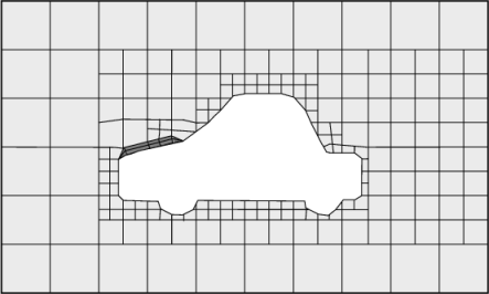
The process of mesh layer addition involves shrinking the existing mesh from the boundary and inserting layers of cells, broadly as follows:
- the mesh is projected back from the surface by a specified thickness in the direction normal to the surface;
- solve for relaxation of the internal mesh with the latest projected boundary vertices;
- check if validation criteria are satisfied otherwise reduce the projected thickness and return to 2; if validation cannot be satisfied for any thickness, do not insert layers;
- if the validation criteria can be satisfied, insert mesh layers;
- the mesh is checked again; if the checks fail, layers are removed and we return to 2.
The layer addition procedure uses the settings in the addLayersControls sub-dictionary in snappyHexMeshDict; entries are listed below. The user has the option of 4 different layer thickness parameters — expansionRatio, finalLayerThickness, firstLayerThickness, thickness — from which they must specify 2 only; more than 2, and the problem is over-specified.
- layers: dictionary specifying layers to be inserted.
- relativeSizes: switch that sets whether the specified layer thicknesses are relative to undistorted cell size outside layer or absolute.
- expansionRatio: expansion factor for layer mesh, increase in size from one layer to the next.
- finalLayerThickness: thickness of layer furthest from the wall, usually in combination with relative sizes according to the relativeSizes entry.
- firstLayerThickness: thickness of layer nearest the wall, usually in combination with absolute sizes according to the relativeSizes entry.
- thickness: total thickness of all layers of cells, usually in combination with absolute sizes according to the
- relativeSizes entry.
- minThickness: minimum thickness of cell layer, either relative or absolute (as above).
- nGrow: number of layers of connected faces that are not grown if points do not get extruded; helps convergence of layer addition close to features.
- featureAngle: angle above which surface is not extruded.
- nRelaxIter: maximum number of snapping relaxation iterations (typcially 5).
- nSmoothSurfaceNormals: number of smoothing iterations of surface normals (typically 1).
- nSmoothNormals: number of smoothing iterations of interior mesh movement direction (typically 3).
- nSmoothThickness: smooth layer thickness over surface patches (typically 10).
- maxFaceThicknessRatio: stop layer growth on highly warped cells (typically 0.5).
- maxThicknessToMedialRatio: reduce layer growth where ratio thickness to medial distance is large (typically 0.3)
- minMedianAxisAngle: angle used to pick up medial axis points (typically 90).
- nBufferCellsNoExtrude: create buffer region for new layer terminations (typically 0).
- nLayerIter: overall max number of layer addition iterations (typically 50).
- nRelaxedIter: max number of iterations after which the controls in the relaxed sub dictionary of meshQuality are used (typically 20).
The layers sub-dictionary contains entries for each patch on which the layers are to be applied and the number of surface layers required. The patch name is used because the layers addition relates to the existing mesh, not the surface geometry; hence applied to a patch, not a surface region. An example layers entry is as follows:
5.4.8 Mesh quality controls
The mesh quality is controlled by the entries in the meshQualityControls sub-dictionary in snappyHexMeshDict; entries are listed below.
- maxNonOrtho: maximum non-orthogonality allowed (degrees, typically 65).
- maxBoundarySkewness: max boundary face skewness allowed (typically 20).
- maxInternalSkewness: max internal face skewness allowed (typically 4).
- maxConcave: max concaveness allowed (typically 80).
- minFlatness: ratio of minimum projected area to actual area (typically 0.5)
- minTetQuality: minimum quality of tetrahedral cells from cell decomposition; generally deactivated by setting large negative number since v5.0 when new barycentric tracking was introduced, which could handle negative tets.
- minVol: minimum cell pyramid volume (typically 1e-13, large negative number disables).
- minArea: minimum face area (typically -1).
- minTwist: minimum face twist (typically 0.05).
- minDeterminant: minimum normalised cell determinant; 1
 hex;
hex;
 0 = illegal cell (typically 0.001).
- minFaceWeight: 0
 0.5 (typically 0.05).
- minVolRatio: 01.0 (typically 0.01).
- minTriangleTwist:
 0 for Fluent compatibility (typically -1).
- nSmoothScale: number of error distribution iterations (typically 4).
- errorReduction: amount to scale back displacement at error points (typically 0.75).
- relaxed: sub-dictionary that can include modified values for the above keyword entries to be used when nRelaxedIter is exceeded in the layer addition process.