[version 14][version 13][version 12][version 11][version 10][version 9][version 8][version 7][version 6]
5.1 Mesh description
This section provides a specification of the way the OpenFOAM C++ classes handle a mesh. The mesh is an integral part of the numerical solution and must satisfy certain criteria to ensure a valid, and hence accurate, solution. During any run, OpenFOAM checks that the mesh satisfies a fairly stringent set of validity constraints and will cease running if the constraints are not satisfied.
By default OpenFOAM defines a mesh of arbitrary polyhedral cells in 3-D, bounded by arbitrary polygonal faces, i.e. the cells can have an unlimited number of faces where, for each face, there is no limit on the number of edges nor any restriction on its alignment. A mesh with this general structure is known in OpenFOAM as a polyMesh. This type of mesh offers great freedom in mesh generation and manipulation in particular when the geometry of the domain is complex or changes over time.
5.1.1 Mesh specification and validity constraints
Before describing the OpenFOAM mesh format, we will first set out the validity constraints used in OpenFOAM. The conditions that a mesh must satisfy are:
5.1.1.1 Points
A point is a location in 3-D space, defined by a vector in units of metres ( ).
The points are compiled into a list and each point is referred to by a label, which
represents its position in the list, starting from zero. The point list cannot contain
two different points at an exactly identical position nor any point that is not part
at least one face.
).
The points are compiled into a list and each point is referred to by a label, which
represents its position in the list, starting from zero. The point list cannot contain
two different points at an exactly identical position nor any point that is not part
at least one face.
5.1.1.2 Faces
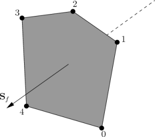
A face is an ordered list of points, where a point is referred to by its label. The ordering of point labels in a face is such that each two neighbouring points are connected by an edge, i.e. you follow points as you travel around the circumference of the face. Faces are compiled into a list and each face is referred to by its label, representing its position in the list. The direction of the face normal vector is defined by the right-hand rule, i.e. looking towards a face, if the numbering of the points follows an anti-clockwise path, the normal vector points towards you, as shown in Figure 5.1.
There are two types of face:
- Internal faces
- Those faces that connect two cells (and it can never be more than two). For each internal face, the ordering of the point labels is such that the face normal points into the cell with the larger label, i.e. for cells 2 and 5, the normal points into 5;
- Boundary faces
- Those belonging to one cell since they coincide with the boundary of the domain. A boundary face is therefore addressed by one cell(only) and a boundary patch. The ordering of the point labels is such that the face normal points outside of the computational domain.
Faces are generally expected to be convex; at the very least the face centre needs to be inside the face. Faces are allowed to be warped, i.e. not all points of the face need to be coplanar.
5.1.1.3 Cells
A cell is a list of faces in arbitrary order. Cells must have the properties listed below.
- Contiguous
- The cells must completely cover the computational domain and must not overlap one another.
- Convex
- Every cell must be convex and its cell centre inside the cell.
- Closed
- Every cell must be closed, both geometrically and topologically
where:
- geometrical closedness requires that when all face area vectors are oriented to point outwards of the cell, their sum should equal the zero vector to machine accuracy;
- topological closedness requires that all the edges in a cell are used by exactly two faces of the cell in question.
5.1.1.4 Boundary
A boundary is a list of patches, each of which is associated with a boundary condition. A patch is a list of face labels which clearly must contain only boundary faces and no internal faces. The boundary is required to be closed, i.e. the sum all boundary face area vectors equates to zero to machine tolerance.
5.1.2 The polyMesh description
The constant directory contains a full description of the case polyMesh in a subdirectory polyMesh. The polyMesh description is based around faces and, as already discussed, internal faces connect 2 cells and boundary faces address a cell and a boundary patch. Each face is therefore assigned an ‘owner’ cell and ‘neighbour’ cell so that the connectivity across a given face can simply be described by the owner and neighbour cell labels. In the case of boundaries, the connected cell is the owner and the neighbour is assigned the label ‘-1’. With this in mind, the I/O specification consists of the following files:
- points
- a list of vectors describing the cell vertices, where the first vector in the list represents vertex 0, the second vector represents vertex 1, etc.;
- faces
- a list of faces, each face being a list of indices to vertices in the points list, where again, the first entry in the list represents face 0, etc.;
- owner
- a list of owner cell labels, the index of entry relating directly to the index of the face, so that the first entry in the list is the owner label for face 0, the second entry is the owner label for face 1, etc;
- neighbour
- a list of neighbour cell labels;
- boundary
- a list of patches, containing a dictionary entry for each patch, declared
using the patch name, e.g. The startFace is the index into the face list of the first face in the patch, and nFaces is the number of faces in the patch.movingWall
{
type patch;
nFaces 20;
startFace 760;
}
5.1.3 Cell shapes
While OpenFOAM supports any shapes of cell, other tools and software generally do not. Therefore conversion of meshes to and from OpenFOAM format often requires the use of defined cell shapes, such as tetrahedra, hexahedra, etc. The functionality is available in a cellShape class that uses a set of shapes defined in a cellModels file in the $FOAM_ETC directory.
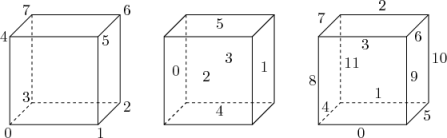 (a) Hexahedron: keyword hex |
 (b) Wedge: keyword wedge |
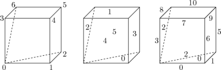
 (c) Prism: keyword prism |
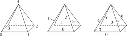 (d) Pyramid: keyword pyr |
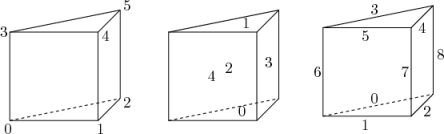
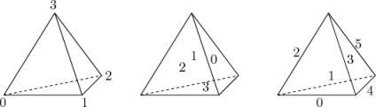 (e) Tetrahedron: keyword tet |
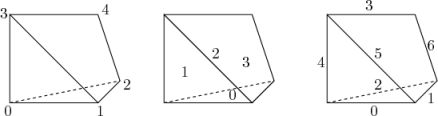 (f) Tetrahedral wedge: keyword tetWedge |
Cells of a given shape are then defined by the ordering of point labels in accordance with the numbering scheme contained in the shape model. For reference, the ordering schemes for points, faces and edges are shown in Table 5.2. Any cell description then consists of two parts: the name of a cell model and the ordered list of labels. Thus, using the following list of points
(
(0 0 0)
(1 0 0)
(1 1 0)
(0 1 0)
(0 0 0.5)
(1 0 0.5)
(1 1 0.5)
(0 1 0.5)
)
(hex 8(0 1 2 3 4 5 6 7))
5.1.4 1- and 2-dimensional and axi-symmetric problems
OpenFOAM is designed as a code for 3-dimensional space and defines all meshes as such. However, 1- and 2- dimensional and axi-symmetric problems can be simulated in OpenFOAM by generating a mesh in 3 dimensions and applying special boundary conditions on any patch in the plane(s) normal to the direction(s) of interest. More specifically, 1- and 2- dimensional problems use the empty patch type and axi-symmetric problems use the wedge type. The use of both are described in section 5.2.2 and the generation of wedge geometries for axi-symmetric problems is discussed in section 5.3.5.