[version 14][version 13][version 12][version 11][version 10][version 9][version 8][version 7][version 6]
6.6 Thermal boundary conditions
For solutions involving thermal energy,
boundary conditions are required for the temperature field
 in
the 0/T file. While
conventional conditions can be used at inlet and outlet patches,
e.g. fixedValue and zeroGradient, respectively, the following
bespoke conditions are available for wall patches.
in
the 0/T file. While
conventional conditions can be used at inlet and outlet patches,
e.g. fixedValue and zeroGradient, respectively, the following
bespoke conditions are available for wall patches.
-
externalTemperature: models heat transfer at an external wall, with various options to specify the heat flux.
-
coupledTemperature: models heat transfer between regions (fluid or solid) in a conjugate heat transfer simulation.
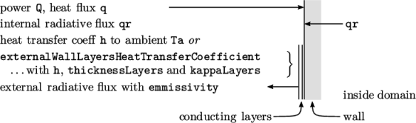
The externalTemperature condition, illustrated in Figure 6.5 , can include one or more of the following heat fluxes.
-
Prescribed power Q (W) or power flux q (W m
 ).
). -
Thermal radiation from inside the domain, qr specifies the radiation field name.
-
Convective heat transfer with a coefficient h and ambient temperature Ta, both a Function1 of time.
-
The coefficient h can alternatively be configured using a specialised externalWallLayersHeatTransferCoefficient field function, which can emulate conduction through additional layers of material on the outside of the wall patch.
-
External thermal radiation with a specified emissivity.
The foamInfo script provides further details and examples of the use of the externalTemperature condition.
foamInfo externalTemperature
wall
{
type externalTemperature;
Ta constant 300;
h constant 10;
value uniform 400;
}
wall
{
type externalTemperature;
Ta constant 300;
h
{
type externalWallLayersHeatTransferCoefficient;
h 10.0;
thicknessLayers (0.1 0.2 0.3 0.4);
kappaLayers (1 2 3 4);
}
value uniform 400;
}
The coupledTemperature condition calculates the heat flux between regions in a conjugate heat transfer simulation. It is shown in Figure 6.6 with regions labelled 1 and 2. The condition is applied at the interface patches of both regions. If we imagine the condition applied to region 1 in the figure, qr specifies the name of the variable for thermal radiation from within region 1, and qrNbr is the name of the variable in the neighbour region, i.e. region 2.
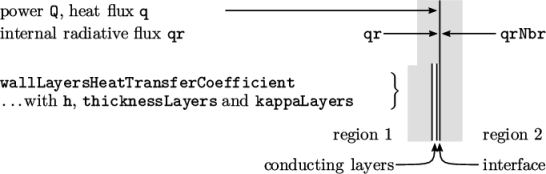
The condition is similar it externalTemperature and can include additional conducting layers at the interface between the regions, e.g. to simulate a contact material, contaminant, liquid film, etc. The conducting layers are specified by the wallLayersHeatTransferCoefficient field function which includes the thicknessLayers and kappaLayers parameters. An example of a coupledTemperature condition with conducting layers is shown below.
wall
{
type coupledTemperature;
h
{
type wallLayersHeatTransferCoefficient;
thicknessLayers (0.1 0.2 0.3 0.4);
kappaLayers (1 2 3 4);
}
value uniform 400;
}